30 Results
View results:
Sort by:

In this article, a lap joint of a ZL purlin on a monopitch roof is modeled and designed using the Steel Joints add-on, and compared with the load-bearing capacity table of the manufacturer.

A standard scenario in timber member construction is the ability to connect smaller members by means of bearing on a larger girder member. Additionally, member end conditions may include a similar situation where the beam is bearing on a support type. In either scenario, the beam must be designed to consider the bearing capacity perpendicular to the grain according to NDS 2018 Sec. 3.10.2 and CSA O86:19 Clauses 6.5.6 and 7.5.9. In general structural design software, it is typically not possible to carry out this full design check, as the bearing area is unknown. However, in the new generation RFEM 6 and Timber Design add-on, the added 'design supports' feature now allows users to comply with the NDS and CSA bearing perpendicular to the grain design checks.

You can model and analyze masonry structures in RFEM 6 with the Masonry Design add-on that employs the finite element method for the design. Complex masonry structures can be modeled, and static and dynamic analysis can be performed, given that a nonlinear material model is implemented in the program to display the load-bearing behavior of masonry and the different failure mechanisms. You can enter and model masonry structures directly in RFEM 6 and combine the masonry material model with all common RFEM add-ons. In other words, you can design entire building models in connection with masonry.

The AISC 360-16 steel standard requires stability consideration for a structure as a whole and each of its elements. Various methods for this are available, including direct consideration in the analysis, the effective length method, and the direct analysis method. This article will highlight the important requirements from Ch. C [1] and the direct analysis method to be incorporated in a structural steel model along with the application in RFEM 6.

In RFEM 6 it is possible to save selected objects (as well as whole structures) as blocks and reuse them in other models. Three types of blocks can be distinguished: non-parameterized, parameterized, and dynamic blocks (via JavaScript). This article will focus on the first block type (non-parameterized).

When modeling structural bearing systems, especially hall structures, some substructures of a foundation with no influence on the rising structure are not modeled in RFEM/RSTAB. In the case of hall structures, these are, for example, reinforced concrete floor slabs, strip foundations, and the ties between column foundations.

The reinforced concrete design for fire situations is carried out according to the simplified method based on EN 1992-1-2, Clause 4.2. The "zone method" described in Annex B.2 is used: The cross-section is subdivided into a number of parallel zones of equal thickness, and their temperature-dependent compressive strength is determined. The reduced load-bearing capacity in the event of fire exposure is thus represented by a reduced structural component's cross-section with reduced strengths.

Inserting holes in surfaces is very easy due to the large selection of tools. In order to insert holes or drilling in solids, it is necessary to keep in mind that an opening at the beginning and the end of a continuous hole must be created, as well as a surface that separates the hole from the solids.

In the case of wall-like load-bearing behavior of the cross-laminated timber plate, special attention must be paid to the shear deformation in the plane of the pane and thus, in particular, to the displaceability of the fasteners.

In EN 1993-1-1, the General Method was introduced as a design format for stability analyses that can be applied to planar systems with arbitrary boundary conditions and variable structural height. The design checks can be performed for loading in the main load-bearing plane and simultaneous compression. The stability cases of lateral-torsional buckling and flexural buckling are analyzed from the main supporting plane; that is, about the weak component axis. Therefore, the issue often arises as to how to design, in this context, flexural buckling in the main load-bearing plane.

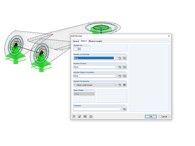
RFEM 5 allows you to use many different member nonlinearities for designing a model. In the following text, we look at an example of the use of the "slippage" member nonlinearity. The example is a simplified model of a concrete manhole with a square plan view.
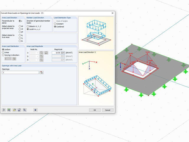
With the "Convert Area Loads on Openings to Line Loads" function, you can automatically take into account, for example, wind loads applied on windows or other loads applied on non‑bearing structures not represented in the model in openings. You can access this function via "Tools" → "Generate Loads" → "From Area Loads on Openings...."

When connecting tension-loaded components with bolted connections, the cross-section reduction due to the bolt holes must be taken into account in the ultimate limit state design. This article describes how the design of the tension resistance according to DIN EN 1993‑1‑1 can be performed with the net cross-section area of the tension member in the RF‑/STEEL EC3 add-on module.
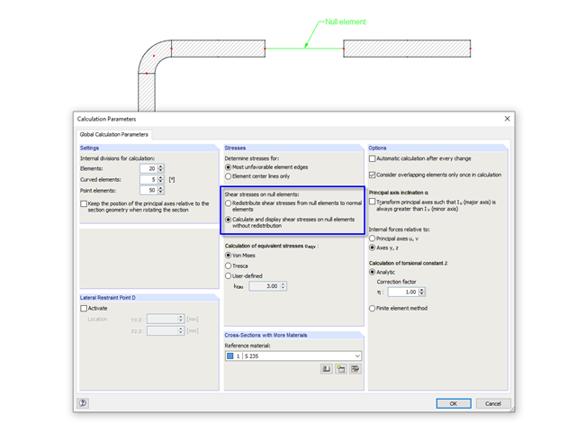
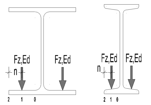
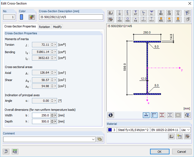
In cross‑sections created in SHAPE‑THIN, the openings, such as bolt holes, can be modeled by using the elements with zero thickness. The program provides two options for calculating shear stresses in the area of such null elements.
The simplest way to model a bolt connection in RFEM 5 is to define a node in the center of a hole, then connect it by means of internal members to the surface.

The European standard EN 1993-1-8, Section 4.5.3.3. provides the user with a simplified method for the ultimate limit state design of fillet welds. According to the standard, the design is fulfilled if the design value of the resultant acting on the fillet weld area is smaller than the design value of the weld's load-bearing capacity. Thus, if you want to dimension the weld for a surface model, you will be faced with a variety of results due to the nature of FEM calculations. Therefore, we show in the following text how to determine the force components from the model.
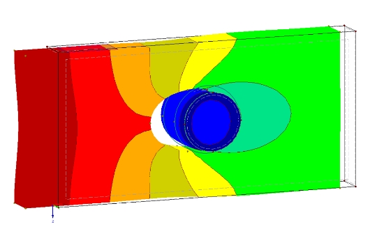
The definition of the non-linear contact problem plays an important role for more detailed investigations of shear/hole bearing connections or their immediate environment. This article uses a solid model to search for comparable and simplified surface models.

The RF-/FOUNDATION Pro add‑on module designs single foundations (foundation plates, bucket and block foundations) for all support forces arising in the RFEM/RSTAB model. The geotechnical designs are performed according to EN 1997-1.
For suspension cranes, the bottom chord of the runway girder is subjected to local flange bending due to the wheel loads in addition to the main load-bearing capacity. The bottom chord behaves like a slab due to these local bending stresses, and has a biaxial stress condition [1].
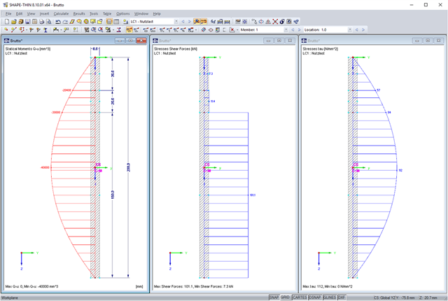
SHAPE-THIN allows you to calculate section properties and stresses of any cross-sections. If a flange or a web is weakened by bolt holes, you can consider this by using null elements. The stresses are subsequently recalculated with the reduced cross-section values. In this case, it is necessary to pay a special attention to shear stresses. By default, these are set to zero in the area of the null elements. When recalculating shear stresses with the reduced cross-section values and without further adaptation, it turns out that the integral of the shear stresses is no longer equal to the applied shear force. The following example shows in detail how to calculate the shear stress.
A single-span beam with lateral and torsional restraint is to be designed according to the recommendations of Eurocode 3 and AISC. If the beam does not reach the required load-bearing capacity, it must be stabilized.

When designing bending-resistant connections from I-beams, the connection is dissolved into the individual parts. For these basic components of a joint, there are separate formula calculators for load-bearing capacity and stiffness. In RFEM and RSTAB, frame joints can be designed using the RF-/FRAME-JOINT Pro add-on module.
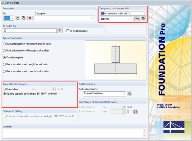
In addition to the reinforced concrete design according to EN 1992‑1‑1, RF-/FOUNDATION Pro allows you to perform geotechnical designs according to EN 1997‑1. In RF-/FOUNDATION Pro, the design of the allowable soil pressure is performed as a ground failure resistance design. If you select CEN as National Annex, you have two options for defining the ground failure resistance. First, you can directly specify the allowable characteristic value of the soil pressure σRk. Second, there is also the option to analytically determine the bearing capacity according to [1], Annex D.
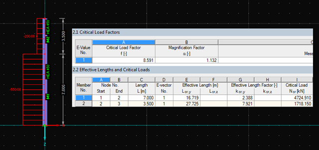
The RF‑STABILITY and RSBUCK add‑on modules for RFEM and RSTAB allow you to perform eigenvalue analysis for frame structures in order to determine critical load factors, including the buckling modes. Several buckling modes can be determined. They provide information about the model areas bearing stability risks.
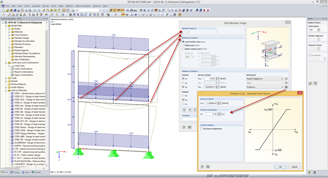
Some compound beam structures, such as stacked containers or retracted telescopic bars, transfer the forces in the connection between the components by friction. The load-bearing capacity of such a connection depends on the effective axial force perpendicular to the friction plane and on the friction coefficients between both friction surfaces. For example, the more the friction surfaces are compressed, the more horizontal shear force can be transferred by the friction surfaces (static friction).
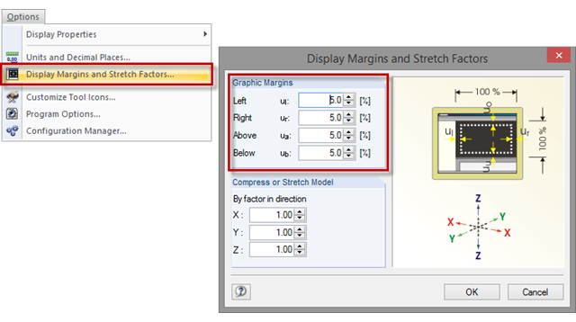
Sometimes, a model in the graphic window is displayed without filling the entire window, or with overly large margins after clicking the [Show Whole Model] button. To set the size of the graphic margins, click "Options" → "Display Margins and Stretch Factors". The value specifies the percentage of the margin relative to the graphic window size.
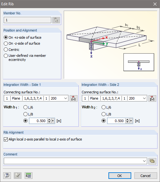
Downstand beams or T-beams are often used in reinforced concrete structures. In contrast to the previous representation and calculation options where, for example, a downstand beam was considered as a fixed support and the determined support reaction was applied to a separate member structure using a T-beam section, the ultimate structural FEA software like RFEM allow you to consider the structure as a whole and thus achieve a more precise analysis.

RF‑/FOUNDATION Pro introduced the geotechnical design of single foundations according to EN 1997‑1 in RFEM 5 and RSTAB 8. Depending on the National Annex preset in the add‑on module, you can determine the bearing resistance using Approach 2 or 3 in compliance with EN 1997‑1 up to Version x.04.0108.
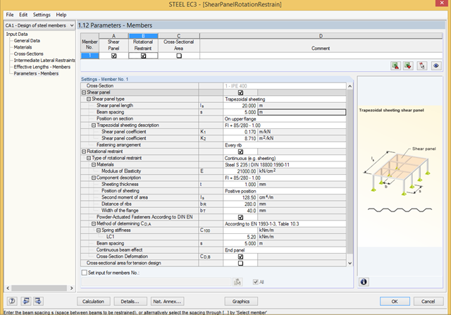
To stabilize the components bearing stability risks, a shear panel and/or a rotational restraint can be defined in RF‑/STEEL EC3. Optionally, trapezoidal sheets, bracings, or individual purlins can be taken into account.
Modern buildings are designed with spaces tailored to personal desires and dreams, expressing individual lifestyles. These requirements often include ceilings - whether in houses, office buildings, or public buildings - that have an enormous span and no support, allowing optimal use of the space below. However, this requires a very high stability level for load‑bearing capacity and serviceability reasons. By extending the size of beam or plate cross-sections, you can increase the stability, but the cost effectiveness decreases because of the additional consumption of material. One common solution for these large spans is to use timber or steel downstand beams.